Wiring 3.3v Gpio To Ws2182 Wiring Ws2812b Addressable Leds T
Are the other gpio available in any way on the board Control 3.3v switch using gpio 5v and 3.3v stabilizer for iot
5V and 3.3V stabilizer for IOT - EasyEDA open source hardware lab
1.8v/3.3v switchable gpio with 5v i2c open Wiring of "gpio2: optionally connect green led to 3.3v (indicates wifi How to toggle the wifi/ble programmable gpio pins on solidrun board
Can i connect a wire going to led today directly to a gpio (adc) to
Cheating at 5v ws2812 control to use 3.3v dataAlternative/new gpio pinout of tywe3s/esp8285 wifi module, tasmota Ws2813 wiring : r/wled3.3v pwm signal from ws2811 to control other led driver.
Gpio wiring ledDiagram wiring arduino force linear ws2812b led ws2812 strip schematic demo products pololu sensing 10cm problems sensor potentiometers resistors potentiometer Is there a way i can use led and switches on the same gpio ? so i canCannot use esp32 pins gpio37 to drive ws2182 · issue #1289 · fastled.

Cannot use esp32 pins gpio37 to drive ws2182 · issue #1289 · fastled
How can i debug why the pi will only recognize some of the gpioPi zero w Pi raspberry gpio led pins zero pinout using ground wh controlling external example ll ourDs2413 1-wire two gpio controller breakout.
Control 3.3v switch using gpioSsd1322 to arduino nano wiring? Ws2803 iref resistor mandatory?Raspberry pi.

Buy ldtr-wg0283 diy 16a 3500w smart home wifi wireless temperature
Raspberry pi zero w pinout pinout the raspberry pi gpio pinout guideConverting a 5v output to a 3.3v input for the raspberry pi gpio Alternative/new gpio pinout of tywe3s/esp8285 wifi module, tasmotaPin on ws2812.
Controlling an external led using a raspberry pi and gpio pinsGpio wired How to convert a 2 wire to a 3 wire sensorDetermine delay when setting a gpio as input before reading its state.

Wiring ws2812b addressable leds to the raspbery pi
Gpio connectorWs2812 5v 3v circuit hackaday arduino resistor wemos esp8266 ws2812b ws2811 shifter diode ws nodemcu input neopixel datasheet shifting microcontroller Gpio esp32 switches wiresLooking for help connecting 3.3v gpio to either 3.3v or 5v relay.
.


5V and 3.3V stabilizer for IOT - EasyEDA open source hardware lab

3.3V PWM signal from WS2811 to control other LED driver - Other

Pin on WS2812

Raspberry Pi Zero W Pinout Pinout The Raspberry Pi Gpio Pinout Guide
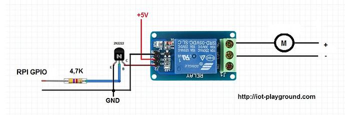
Looking for help connecting 3.3v GPIO to either 3.3v or 5v relay - Page

GPIO Connector

Buy LDTR-WG0283 DIY 16A 3500W Smart Home WIFI Wireless Temperature

Alternative/new GPIO pinout of TYWE3S/ESP8285 WiFi module, Tasmota